Gigabit Ethernet 1000BASE-T
TABLE OF CONTENTS 1997 Gigabit Ethernet Alliance
- Introduction
- The Case for a Copper Gigabit Ethernet Solution
- 1000BASE-T Overview
- Standards Development Process
- Interoperability
- How Does It Work?
- The Cabling Issue
- The Design Approach
GIGABIT ETHERNET OVER 4-PAIR 100 OHM CATEGORY 5 CABLING
Introduction
With the dramatic increases in desktop computing power driven by Intranet-based operations and the increasing demands for time-sensitive delivery between networked users, a new generation, high-bandwidth Ethernet LAN is evolving. The rapid adoption of 100Mb/s or Fast Ethernet, due to low cost and compatibility with existing LANs, underscores the popularity of Ethernet technology. With 1000 Mb/s Ethernet following close behind, Ethernet technology is poised as the network solution for the next century.
Gigabit Ethernet has been demonstrated to be a viable solution for increased bandwidth requirements for growing networks [reference to GEA white paper]. Early implementation of the technology will be in high-speed backbones and specialized workgroups. As desktop speeds increase and LAN application patterns change, Gigabit Ethernet will begin to migrate to the desktop for general applications. To be most effective, Gigabit Ethernet must be capable of operating over widely-installed cable plants. Worldwide, the most widely deployed cable plant is copper UTP (Unshielded Twisted Pair) wiring. In fact, four-pair, 100 ohm, Category 5 cabling is the most widely deployed cabling system for high-speed LANs.
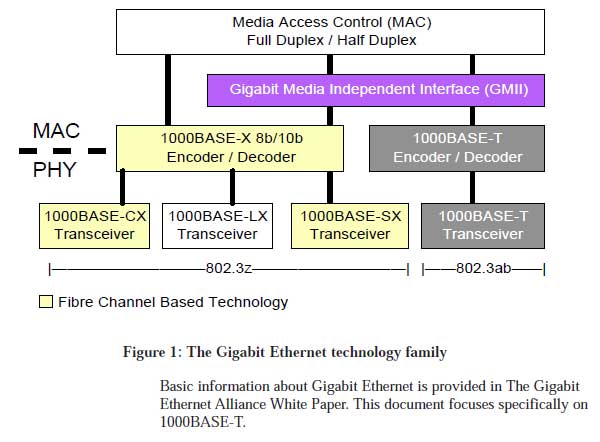
Ethernet standards are created and maintained by the 802.3 working group of the IEEE LAN-MAN Standards Committee. Since 1995, a task force known as 802.3z has been working on fiberoptic and a shielded jumper cable assembly (“short-haul copper”) solutions for Gigabit Ethernet. In the spring of 1997, a new task force was formed to work on a “long-haul copper” solution based on four pairs of Category 5 cabling wiring. This 802.3ab task force is working to standardize a Gigabit Ethernet link of 100 meters maximum length on four pairs of Category 5 UTP cabling. The Gigabit Ethernet standards define an interface (called the GMII) to the Ethernet Media Access Control (MAC) layer, management, repeater operations, topology rules, and four physical layer signaling systems: 1000BASE-SX (short wavelength fiber), 1000BASE-LX (long wavelength fiber), 1000BASE-CX (short run copper) and 1000BASE-T (100-meter, four-pair Category 5 UTP). Figure 1 below shows the relationship of the various members of the Gigabit Ethernet technology family.
THE CASE FOR A COPPER GIGABIT ETHERNET SOLUTION
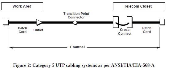
1000BASE-T extends the envelope of Gigabit Ethernet by enabling operation over the extensive installed base of legacy Category 5 cabling systems and, by default, the Category 5 cabling systems currently being installed. The distribution of four-pair Category 5 cabling extends from the work area to the equipment room and between equipment in the equipment room, thus enabling connectivity to switched and shared gigabit services for both high-bandwidth work area computing and server farms. (See Figure 2.)
Used in conjunction with Full Duplex Repeaters, 1000BASE-T can provide highly cost-effective shared gigabit service. Full Duplex Repeaters (FDRs), also called buffered distributors, offer the traditional low-cost shared media operation of repeaters, but with support for full-duplex operation. When coupled with 1000BASE-T, FDRs will offer an easy-to-manage, high-burst rate, shared-media solution capable of supporting both end users and server farms. When used with a server farm, this technology offers the most cost-effective way to aggregate one gigabit of server support.
Many potential Gigabit Ethernet technology adopters are already calling for a gigabit UTP copper solution because it will allow them to use their existing copper cable plant and because the cost-of-entry for copper solutions has traditionally been lower than fiber-based solutions.
1000BASE-T OVERVIEW
1000BASE-T provides half-duplex (CSMA/CD) and full-duplex 1000Mb/s Ethernet service over Category 5links as defined by ANSI/TIA/EIA-568-A. Topology rules for 1000BASE-T are the same as those used for 100BASE-T. Category 5 link lengths are limited to 100 meters by the ANSI/TIA/EIA-568-A cabling standard. Only one CSMA/CD repeater will be allowed in a collision domain 1000BASE-T uses the same Auto-Negotiation system employed by 100BASE-TX, simplifying the task of gradually integrating it into legacy Ethernet networks. In addition, many of the companies working on 1000BASE-T have indicated they will produce dual-speed PHYs capable of both 100 Mb/s and 1000 Mb/s operation. This ensures that 1000BASE-T devices can “fall back” to 100BASE-TX operation, thus providing a flexible method for upgrading systems.
Cable plants conforming to current TIA/EIA-568-A (1995) requirements should support 1000BASE-T operation. Individual links should be tested per ANSI/TIA/EIA-TSB-67- “Transmission Performance Specifications for Field Testing of Twisted Pair Cabling System” with the additional test parameters for FEXT (ELFEXT) loss and return loss that will be included as an addendum to ANSI/TIA/EIA-568-A.
Cabling test tool manufacturers should have these capabilities added to their products before the 1000BASE-T standard is released. Category 5 cabling which does not pass TSB-67 testing (including addendum parameters) may not have been installed correctly. For example, the amount of untwisting in a pair as a result of termination to connecting hardware cannot exceed 13 mm (0.5 in), or the connecting hardware may not meet current ANSI/TIA/EIA-568-A requirements and may need upgrading. All Category 5 links should be tested before using either 1000BASE-T or 100BASE-T.
Some companies plan to have sample quantities of their initial 1000BASE-T components (PHY chips) by mid 1998, with prototype products following shortly thereafter. The first customer shipments of 1000BASE-T products should occur in late 1998. Members of the 1000BASE-T development team are working to ensure that conformance test suites for 1000BASE-T are developed in parallel with the standards effort, so the test suites will be in place when the first products arrive. This will enable testing of components and products before they are released to market.
STANDARDS DEVELOPMENT PROCESS
note this was written in 1997
Ethernet standards are created and maintained by the 802.3 working group of the IEEE LAN-MAN Standards Committee. For the last two years, a task force known as 802.3z has been working on fiberoptic and shielded copper jumper solutions for Gigabit Ethernet. In the spring of 1997, a new task force with special expertise in Digital Signal Processing (DSP) technology was formed to work on a “longhaul copper” solution based on UTP wiring. This 802.3ab task force is working to standardize a Gigabit Ethernet link of 100 meters maximum length on four pairs of Category 5 UTP cabling.
The 802.3z task force is responsible for 1000BASE-X, which defines MAC changes, a Gigabit Media Independent Interface, management, and general requirements for 1000 Mb/s operation, as well as a set of
physical layer interfaces based on physical layer technology originally developed for Fibre Channel. The 802.3ab task force is developing the 1000BASE-T standard, which adds an additional physical layer
signaling system to the basic technology defined by 1000BASE-X. 1000BASE-X is now essentially complete and undergoing the formal ballot processes required for IEEE 802 approval. The target date for approval of the 1000BASE-X standard is March 1998. 1000BASE-T is operating with a longer schedule to accommodate the complex signaling issues involved with running 1000 Mb/s over standard Category 5 wiring. The first draft of what will become the 1000BASE-T standard is expected in November 1997; approval of the standard should come in the second half of 1998.
Interoperability
note this was written in 1997
Although not a formal part of the standards development process, conformance and interoperability testing are an essential part of bringing a new networking technology to market. The standard defines what to test, but an enabling organization is required to translate standards requirements into test suites and provide a mechanism for applying them uniformly to products.
A Gigabit Ethernet Consortium (GEC) was founded in July 1997 to conduct conformance and interoperability testing for all Gigabit Ethernet technologies. The GEC is housed at the University of New Hampshire’s Interoperability Laboratory (IOL), which also houses similar consortia for testing 10BASE-T, 100BASE-T, ATM, Fiber Channel, and Token Ring.
GEA teams have been working since the summer of 1997 to define test suites for 1000BASE-X technologies. The GEA is encouraging member companies to participate in 1000BASE-T test suite development activities with the goal of having initial suites defined by mid-1998.
1000BASE-T - HOW DOES IT WORK?
This section provides a brief overview of the technical foundations to 1000BASE-T. It covers cabling issues, the proposed technical approach, and a discussion of how the 1000BASE-T standard builds upon techniques pioneered in Fast Ethernet and advanced Digital Signal Processing.
The Cabling Issue
Category 5 cabling as defined by ANSI/TIA/EIA-568-A is currently the most commonly used data grade cabling in the US. A recent Sage study indicated that more than 72 percent of their sample of network installations reported having Category 5 cabling installed. 1000BASE-T is intended to provide a Gigabit Ethernet solution for these legacy networks. Accordingly, the Project Authorization Request (PAR) for the 1000BASE-T project specifically requires operation on four pair, 100 ohm Category 5 balanced copper cabling as defined by ANSI/TIA/EIA-568-A, or its equivalent as built from material specified by ISO/IEC 11801:1995 that meets the channel performance parameters specified in ANSI/TIA/EIA-568-A ANNEX E.
(There is currently a proposal to add a Category 5 channel specification to ISO/IEC 11801 that would provide the same channel performance parameters specified in ANSI/TIA/EIA-568-A.)
Transmitting a 1000 Mb/s data stream over four pairs of Category 5 twisted pair cables presents several design challenges to the transmission system designer (and standards developer). The challenges are due to signal attenuation, echo, return loss, and crosstalk characteristics of cables, as well as electromagnetic emissions and susceptibility. (See Figure 3 below.)
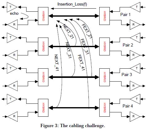
Attenuation is the signal loss of the cabling from the transmitter to the receiver. Attenuation increases with frequency, so designers are challenged to use the lowest possible frequency range that is consistent with the required data rate.
Echo is a by-product of dual-duplex operation, where both the transmit and receive signal occupy the same wire pair. The residual transmit signal due to the trans-hybrid loss and the cabling return loss combine to produce an unwanted signal referred to here as echo.
Return loss is a measure of the amount of power reflected due to cabling impedance mismatches.
Crosstalk is unwanted signals coupled between adjacent wire pairs. Since 1000BASE-T will use all four wire pairs, each pair is affected by crosstalk from the adjacent three pairs. Crosstalk is characterized in reference to the transmitter. Near-end crosstalk (NEXT) is crosstalk that appears at the output of a wire pair at the transmitter end of the cable and far-end crosstalk (FEXT) is crosstalk that appears at the output of a wire pair at the far end of the cable from the transmitter. Equal level far-end crosstalk (ELFEXT) is FEXT with the cable attenuation removed to provide equal-level comparisons, i.e., crosstalk and receive signals voltages are compared at the end of the cabling opposite the transmitter. Designers must incorporate technology to keep crosstalk from interfering with symbol recovery operations in the receiver.
Additional specifications for FEXT (ELFEXT) loss and return loss, which are not currently specified by TIA/EIA-568-A ANNEX E, have been developed to characterize the vast majority of the installed base of Category 5 cabling built to ANSI/TIA/EIA-568-A and/or ISO/IEC 11801 clauses 6, 8 & 9. A currently proposed addendum to ANSI/ANSI/TIA/EIA-568-A will include the additional transmission performance specifications and field test parameters for FEXT (ELFEXT) loss and return loss.
A verification of the installed cabling performance per the field test specification of ANSI/TIA/EIA-TSB- 67- “Transmission Performance Specifications for Field Testing of Twisted Pair Cabling System” with the additional test parameters for FEXT (ELFEXT) loss and return loss (to be released as an addendum to ANSI/TIA/EIA-568-A) will be recommended.
A transmission system operating over unshielded cable must be capable of withstanding radiated energy from other sources, including AM, CB, short wave radio, and other external transmitters. Standards such as EN50082-1 and IEC 1000-4-3 (IEC 801-3 Level 2) also specify a required tolerance to a 3 V/m continuous wave source above 27 MHz.
A further design objective is to maximize the tolerance to background and impulse noise. Impulse noise can be generated by power line transients, electrical fast transients, electro-static discharge (ESD), and other sources. Although there is no precise specification from existing standards concerning the minimum tolerance to impulse noise that could be acceptable for 1000BASE-T, a general goal is to strive for as much tolerance as possible.
The Design Approach
The characteristics of Category 5 cabling and the regulatory constraints identified above create a significant challenge in defining the 1000 Mb/s physical layer. Fortunately, digital communications techniques developed in recent years can be used to design robust transceivers that are capable of achieving reliable operations in a Category 5 cabling environment. 1000BASE-T takes advantage of several of these techniques to transform the desired bit rate into an acceptable baud rate (signaling events per second) for operation over 4-pair Category 5 cabling.
•Use existing 4-pair Category 5 cable. To ensure proper operation at full link lengths, the cable must conform to the requirements of ANSI/TIA/EIA-568-A (1995).
• Use all four pairs in the cable to keep symbol rate at or below 125 Mbaud.• Use PAM-5 coding to increase the amount of information sent with each symbol.
• Use 4D 8-state Trellis Forward Error Correction coding to offset the impact of noise and crosstalk.
• Use pulse shaping techniques to condition the transmitted spectrum.
• Use state-of-the-art DSP signal equalization techniques to manage the problems of noise, echo and crosstalk interferences, and to ensure a bit error rate of 10-10.
Technical descriptions of these techniques are described in the remainder of this subsection. The block diagram of a 1000BASE-T transceiver (shown in Figure 4) shows the relationships among the
various components.
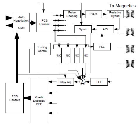
Figure 4: Block diagram of the 1000BASE-T transceiver.
Dual-duplex transmission consists of transmitting and receiving data simultaneously in both directions (full-duplex transmission) on each of the four wire pairs, minimizing the symbol rate (and thus, the occupied signal bandwidth) on each wire pair by one half, as compared to unidirectional transmission and reception. Hybrid circuits are used to enable bi-directional transmission over single wire pairs by filtering out the transmit signal at the receiver. (See Figure 5 below.)
Hybrid networks with good trans-hybrid loss minimize the amount of transmitter signal that is coupled into the receiver but still cannot remove all of the transmit signal. The residual transmit signal from the hybrid and the return loss of the cable require that cancellers are added to each wire pair to remove the transmit echo signal.
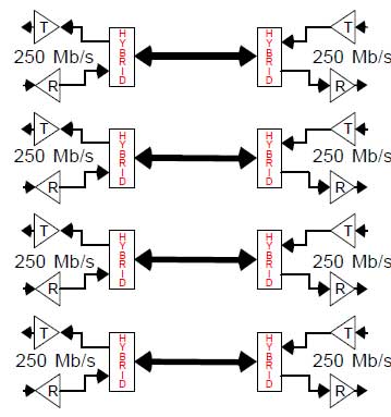
Figure 5: Dual-duplex transmission uses hybrids to separate transmit and receive signals on each wire pair.
5-level PAM provides better bandwidth utilization than binary signaling, where each transmitted symbol represents just one bit (0 or 1.). In 5-level PAM, each transmitted symbol represents one of five different levels (-2, -1, 0, + 1, +2). Since each symbol can represent two bits of information (four levels used to represent two bits, plus an extra fifth level used in the Forward Error Correction coding), the symbol rate, and therefore also the signal bandwidth, are reduced by a factor of two. The costs of multilevel signaling include the need for a higher signal-to-noise ratio for a given error rate, the use of multi-bit D/A and A/D converters and the need for better receiver equalization.
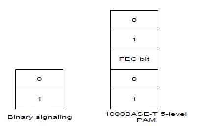
Figure 6: Binary vs 5-level PAM coding
Forward Error Correction (FEC) provides a second level of coding that helps to recover the transmitted symbols in the presence of high noise and crosstalk. The 4-Dimensional 8-State Trellis Forward Error Correction encoding facilitates recovering the transmitted symbols in the presence of high noise and crosstalk. This technique improves the signal-to-noise ratio at the “slicer”-the decision element in the Analog-to-Digital (A/D) converter in the receiver.
Pulse shaping matches the spectral characteristics of the transmitted signals to those of the channel in order to maximize the signal-tonoise ratio. This is achieved with a combination of analog and digital filtering elements used at the transmitter, at the receiver, or both. Pulse shaping is used to minimize the transmitted signal energy at frequencies where distortion and disturbances are significant, to reduce both low- and high frequency signal components, and to reject highfrequency external noise components. The pulse shaping techniques used by 1000BASE-T transmitters improve the potential for meeting class B emission specifications. Through pulse shaping the 1000BASE-T transmitted signal spectrum will be essentially identical to the 100BASE-TX spectrum.
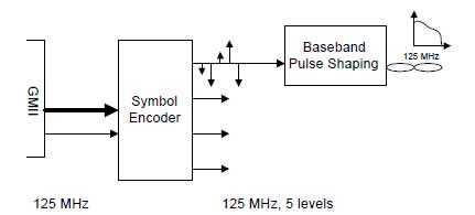
Figure 7: Pulse shaping produces a 1000BASE-T signal spectrum that matches the 100BASE-TX spectrum.
Signal equalization is used to compensate for signal distortion introduced by the communication channel. Linear digital equalization is usually provided by a finite impulse response (FIR) filter. However, linear equalizers color the noise in the receiver. This is especially true as frequency increases and noise coupling becomes worse. The higher the bandwidth of the coding scheme, the more aggressive the equalization and, hence, the greater the high frequency noise boost. Nonlinear equalization is usually provided by a decision-feedback equalizer (DFE) and often provides better signal equalization than linear equalization, especially when the transmission medium introduces strong signal attenuation within specific frequency regions. Unlike a linear equalizer, a DFE does not modify the noise. Therefore, using a DFE does not enhance high-frequency noise.
However, using a DFE to equalize the channel is prone to error propagation, where a single error causes mis-equalization and further errors. One solution to this problem is to use multiple DFEs.
Scrambling is used to randomize the sequence of transmitted symbols and avoid the presence of spectral lines in the transmitted signal spectrum. Scrambling also creates essentially uncorrelated data symbols, which improves operation of the adaptive receiver functions.
Many of the principles and techniques proposed for the 1000BASE-T design approach have already been employed in three 100BASE-T (Fast Ethernet) copper physical layer solutions:
• 100BASE-TX, which runs on 2 pairs of Category 5 cabling with a 125 Mbaud symbol rate and binary encoding,
• 100BASE-T4, which runs on 4 pairs of Category 3 or better cabling with a 25 Mbaud symbol rate and ternary encoding, and
• 100BASE-T2, which runs on 2 pairs of Category 3 or better cabling with a 25 Mbaud symbol rate with quinary encoding and DSP processing to handle the potential problems of alien signals in adjacent wire pairs (alien crosstalk.)
100BASE-TX demonstrates that it is possible to send a symbol stream over Category 5 cable at 125 Mbaud. 100BASE-T4 demonstratestechniques for sending multi-level coded symbols over four pairs. 100BASE-T2 demonstrates the use of digital signal processing (DSP), five-level coding, and simultaneous two-way data streams while dealing with alien signals in adjacent pairs.
Participants in the 1000BASE-T development effort are making aggressive use of simulation tools to evaluate alternative technical approaches, following on earlier simulation efforts used to develop 100BASE-T2. While exploring alternative approaches to line coding and forward error correction techniques, the engineers simulated their own proposals as well as those of the other participants. These simulations have been done both in Matlab and in C. The C simulations have established the necessary confidence that the Bit Error Rate (BER) requirements can be met in the presence of ECHO, NEXT, and FEXT. The simulations also have established that significant levels of external noise (>80mv p-p) can be tolerated. The large amounts of simulation work that have been done significantly increase the conviction that reliable Gigabit Ethernet over copper is both feasible and
practical.
